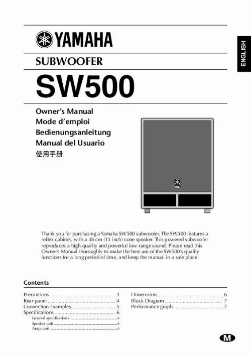
Notice YAMAHA SW500
Liens commerciaux


Extrait du mode d'emploi YAMAHA SW500
Les instructions détaillées pour l'utilisation figurent dans le Guide de l'utilisateur.
If two signals are input at the same time, they are mixed inside the subwoofer. G OUTPUT THRU jacks A and B These are XLR-type balanced output jacks. Connect these jacks to another subwoofer to route signals input from INPUT jacks A and B to the subwoofer. H OUTPUT HIGH PASS jacks A and B These are XLR-type balanced output jacks. Connect these jacks to the main speakers to cut the range below 100 Hz of signals input from INPUT jacks A and B and route them to the main speakers. I POWER indicator This indicator lights up green when you turn the POWER switch ON. J CLIP indicator This indicator lights up red if the output level is too high. In this case, lower the level using the LEVEL control or lower the input level. 4 Connection Examples q Using two SW500s Powered speaker L Powered speaker R Main speaker L Main speaker R Amp TEMP PROTECTION A PROTECTION B POWER WATTS/8 INPUT WATTS/8 INPUT CHANNEL A 18 20 25 30 16 14 12 10 8 20 25 CHANNEL B 18 16 14 12 10 8 6 4 2 00 0 0. 01 0. 0 5 10 CLIP/LIMIT 50 100 200 300 0. 01 0. 0 5 10 CLIP/LIMIT 50 100 200 300 50 40 0 30 20 1 5 2 0 2 4 5 PEAK +dB 50 40 0 30 20 1 5 2 0 2 4 5 PEAK +dB 6 30 4 2 00 0 35 50 CHANNEL A POWER AMPLIFIER CHANNEL B PROFESSIONAL SERIES 35 50 ON/ OFF INPUT (+4dB) OUTPUT THRU OU TPUT HIGH PASS 100Hz INPUT (+4dB) OUTPUT THRU OU TPUT HIGH PASS 100Hz INPUT (+4dB) (+4dB) (+4dB) OUTPUT THRU OU TPUT HIGH PASS 100Hz INPUT (+4dB) (+4dB) OUTPUT THRU OU TPUT HIGH PASS 100Hz (+4dB) PARALLEL PARALLEL PARALLEL PARALLEL PARALLEL PARALLEL PARALLEL PARALLEL SW500 L R SW500 SW500 L R SW500 Mixer Mixer q Using a single SW500s Powered speaker L Powered speaker R INPUT (+4dB) OUTPUT THRU OU TPUT HIGH PASS 100Hz (+4dB) PARALLEL PARALLEL SW500 L R Mixer 5 Specifications General specifications Type Bass Reflex powered subwoofer Frequency Range 40120 Hz (10 dB) Maximum Output Level 122 dB (1 m on Axis) Dimensiones (W × H × D) 480 × 619 × 590 mm Weight 37 kg Installation pole diameter 35 mm (1. 375") Accessories Power cable 2. 5 m (AC inlet type) Speaker unit Speaker Unit 38 cm cone (8) Enclosure Type: Bass Reflex Amp. [...] · This unit is heavy. Use two or more people to carry it. · Do not touch the power plug with wet hands. Doing so is a potential electrical shock hazard. · XLR-type connectors are wired as follows: pin 1: ground, pin 2: hot (+), and pin 3: cold (). · Using a mobile telephone near this unit may induce noise. If noise occurs, use the telephone away from the unit. · Do not use the speakers at uncomfortably loud level. Otherwise, you may damage your hearing. · Subwoofer SW500 comes with a metal socket for installing the speaker stand. Use a speaker stand pole that is one meter or shorter. Troubleshooting --If the unit shuts down during use-- If the CLIP indicator lights up often and you use this unit for a long period of time, the thermostat inside the power transformer will turn the power off. In this case, turn the POWER switch off, wait for a while (about one hour) until the the power transformer cools down, then resume using the unit at a lower input level. Be sure to lower the input level so that the CLIP indicator lights up only momentarily. 3 Rear panel C D SUBWOOFER CONTROL POWER SUBWOOFER MODEL SW500 9 0 80 CUTOFF FREQ. 100 0 LEVEL 10 CLIP E NORM REV PHASE INPUT (+4dB) OUTPUT THRU OU TPUT HIGH PASS 100Hz (+4dB) PARALLEL POWER ON / OFF A A B AC IN B H PARALLEL F G A POWER switch This switch turns the power to the SW500 on and off. When this switch is turned on, the green power indicator (9) lights up. B AC IN connector Connect the included power cable here. C CUTOFF FREQ. control This control enables you to adjust the cutoff frequency in the range of 80 through 100 Hz depending on the speakers you are using with the SW500 and your personal preferences. D LEVEL control This control enables you to adjust the sound volume level. The maximum level is at the scale setting of 10, and the minimum level is at the scale setting of 0. If the level is too high, the CLIP indicator (J) lights up red. In this case, lower the level. E PHASE switch This switch enables you to select a phase. You will usually set this switch to "NORM". However, the "REV" setting may improve low-range sounds, depending on the type and location of the entire speaker system. Try both settings and select the one with a better-sounding low-range output. F INPUT jacks A and B These are XLR-type balanced input jacks. [...]..
Téléchargez votre notice ! Téléchargement gratuit et sans inscription de tous types de documents pour mieux utiliser votre YAMAHA SW500 : mode d'emploi, notice d'utilisation, manuel d'instruction. Cette notice a été ajoutée le Samedi 10 Octobre 2008.
Vous pouvez télécharger les notices suivantes connexes à ce produit :
Vos avis sur le YAMAHA SW500
 Excellent produit
, exellent caisson de basse.


