Notice YAMAHA RC-D24
Liens commerciaux


Extrait du mode d'emploi YAMAHA RC-D24
Les instructions détaillées pour l'utilisation figurent dans le Guide de l'utilisateur.
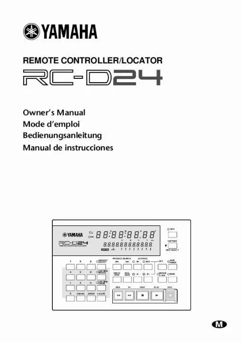
This indicator works only if supported by the D24 system software. C Counter The counter shows the current position in hours, minutes, seconds, and frames (00:00:00. Hour H Min M Sec S fr F 00 00 00 00 H M S F ms 000000000000 Hour Min Sec fr sub-fr D Message area The message area of the display more or less corresponds to the 2nd line of the D24's display, and shows captured positions, locate point positions, project numbers, locate memory numbers, take numbers, remote unit IDs, and tracks selected for recording. Time information is displayed in hours, minutes, seconds, frames, and sub-frames (00:00:00. LAST REC IN, LAST REC OUT, A, and B point values are identified using the prefixes shown here. -- LAST REC IN point -- LAST REC OUT point -- A point -- B point Transport Controls PROJECT SEARCH 5 4 3 2 1 RTN TO ZERO ROLL BACK LAST REC OUT IN SET AUTO PUNCH A B REPEAT A B REHE 6 7 8 9 REW FF STOP PLAY REC J K L M N A A & B buttons & indicators These buttons are used to set and locate the A and B points. The A and B indicators light up when the respective A or B point is set. B ROLL BACK button This button is used to roll back from the current position in steps of between 1 and 30 seconds, the default being 5 seconds. RC-D24--Owner's Manual Touring the RC-D24 4 C RTN TO ZERO button This button is used to locate the zero position. D LAST REC IN & OUT buttons & indicators These buttons are used to set and locate the LAST REC IN and LAST REC OUT points. The IN and OUT indicators light up when the respective IN or OUT point is set. E PROJECT SEARCH buttons These buttons are used to search for projects. Pressing the [ ] button selects the top of the current project. Pressing the [ ] button selects the top of the next project. F AUTO PUNCH button & indicator This button selects the Auto-Punch In/Out function. The AUTO PUNCH indicator flashes when this function is on. G SET button This button is used in conjunction with the LAST REC [IN], LAST REC [OUT], [A], and [B] buttons to set the LAST REC IN, LAST REC OUT, A, and B points, respectively. It's also used in conjunction with the [RTN TO ZERO] button to set the relative zero position. [...] Refer to the D24 Owner's Manual for detailed information. RC-D24 Operating Notes The RC-D24 draws its power from the connected D24 and can be turned on or off either before or after the D24. If the RC-D24 is off, but the connescted D24 is on for normal poeration, there's a possibility that noise from the remote cable may cause the D24 to malfunction. To prevent this, disconnect the RC-D24 from the D24, or turn on the RC-D24. In a multiple-unit system, the RC-D24 can control the entire system through Chase mode or individual D24s. See "Selecting D24s in Multiple-Unit Systems" on page 8 for more information. Unlike the D24, which has two lines in the message area of the display, the RC-D24 display has just one line, which more or less corresponds to the 2nd line of the D24 display. On the RC-D24, tracks are selected for recording using the keypad number buttons. See "Selecting Tracks for Recording" on page 9 for more information. The RC-D24 does not have a JOG/DATA dial, so although it can be used for auto punch in/out recording, the Audition Take and Fix Take functions cannot be controlled remotely. Use the D24 controls when you want to use these functions. RC-D24--Owner's Manual Touring the RC-D24 2 Touring the RC-D24 This section tours around the RC-D24's control surface and rear panel, explaining the purpose of each control and connector. Control Surface ABS ms 00 00 00 00 H M S F ms READY UNIT 1 2 3 4 5 6 7 8 H M S F CAPTURE REMOTE CONTROLLER/LOCATOR UNIT SELECT 7 8 9 PROJECT SELECT PROJECT SEARCH LAST REC OUT IN SET AUTO PUNCH 4 5 6 LOC MEM RECALL RTN TO ZERO ROLL BACK A B REPEAT A B REHE 1 2 3 LOC MEM STORE REW FF STOP PLAY REC 0 CANCEL ENTER LOCATE The RC-D24 control surface is explained in the following sections. Display 12 3 ms 00 00 00 00 H M S F ms H M S F REMOTE CONTROLLER/LOCATOR 000000000000 READY UNIT 1 2 3 4 5 6 7 8 4 A ms indicator This indicator lights up when the D24 counter is set to display milliseconds instead of sub-frames. This indicator works only if supported by the D24 system software. [...]..
Téléchargez votre notice ! Téléchargement gratuit et sans inscription de tous types de documents pour mieux utiliser votre autres YAMAHA RC-D24 : mode d'emploi, notice d'utilisation, manuel d'instruction. Cette notice a été ajoutée le Mardi 4 Avril 2008.
Vous pouvez télécharger les notices suivantes connexes à ce produit :

