Notice TOSHIBA TCB-IFCB-4E2 - INSTALLATION MANUAL
Liens commerciaux


Extrait du mode d'emploi TOSHIBA TCB-IFCB-4E2
Les instructions détaillées pour l'utilisation figurent dans le Guide de l'utilisateur.
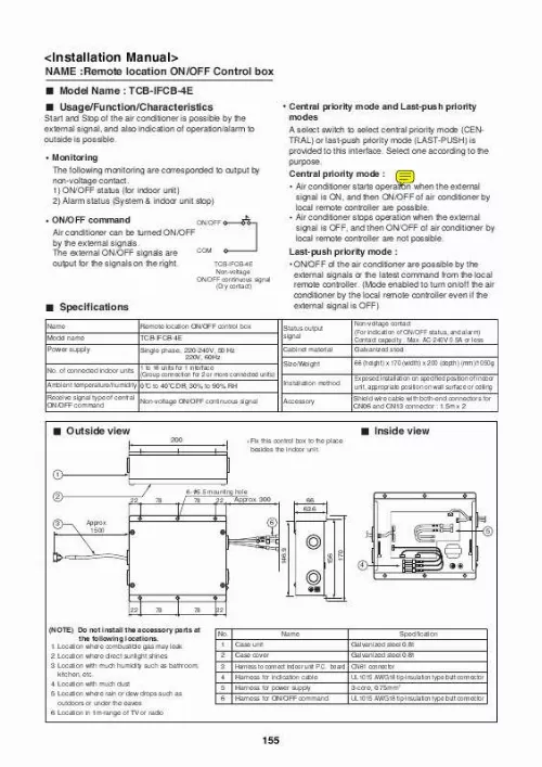
minal L1 L2 Non-voltage ON/OFF continuous signal (Note) * For connecting, be sure to use the attached cables. * Cables other than connecting cables should be required at the site. * Fix the cables surely by using the holes for fixation. Power supply MAX. 240V 0.5A Cable specifications (Local supply) Power supply cable *1 Up to 80m : 3-core, 0.75mm2 Up to 500m : 2-core or 3-core, 0.75mm2 Up to 200m : 3-core, 0.75mm2 Up to 400m : 3-core, 1.5mm2 ON/OFF command signal cable Indication signal cable *1 L1 ON operation lamp L2 Alarm indication lamp Central panel (Required at the site) *1) In conformity with design 60245 IEC 57 Selecting of Central priority/Last-push priority The select switch has been previously set to LAST-PUSH side on shipment from the factory. When using the air conditioner with central priority, remove the cover of interface adapter, and select "CENTRAL" side of the select switch (SW 1) at near the center of P.C. board. (CAUTION) Be sure to turn off the power supply of interface adapter before selecting one side on the select switch. Notes on connecting relays (Relays are used for central indication in order to prevent malfunction by surge absorber.) a. To drive induction load with DC power Diode OPERATION Diode ALARM COM Interface side Central side Wiring method (1) Power supply cable, earth, and indication signal cable must be connected in this control box. Detach the lid of the control box, and connect the cables with the terminal according to the purpose. (2) Be sure to fix the cable with the cable clamp. (Note) Mount diodes to the both ends of the relay coil. Select a diode of which back voltage tightness is 10 times or more of the use voltage, and forward current is more than the load current. b. To drive induction load with AC power Surge absorber RY OPERATION RY Surge absorber ALARM Indication signal cable Power supply cable COM Interface side Central side Cable clamp Earth terminal Cable clamp (Note) Mount surge absorbers to both ends of the relay coil. Use a surge absorber of which voltage tightness is 350V AC/500V DC or more. 156 [...] the local remote controller. (Mode enabled to turn on/off the air conditioner by the local remote controller even if the external signal is OFF) Status output signal Cabinet material Size/Weight Installation method Accessory Non-voltage contact (For indication of ON/OFF status, and alarm) Contact capacity : Max. AC 240V 0.5A or less Galvanized steel 66 (height) x 170 (width) x 200 (depth) (mm)/1050g Exposed installation on specified position of indoor unit, appropriate position on wall surface or ceiling Shield wire cable with both-end connectors for CN06 and CN13 connector : 1.5m x 2 Power supply No. of connected indoor units Ambient temperature/humidity 0 C to 40 C DB, 30% to 90% RH Receive signal type of central Non-voltage ON/OFF continuous signal ON/OFF command Outside view 200 Fix this control box to the place besides the indoor unit. Inside view 1 2 6- 5.5 mounting hole Approx. 300 78 22 22 78 66 63.6 5 3 Approx. 1500 6 146.9 156 170 4 22 78 78 22 (NOTE) Do not install the accessory parts at the following locations. 1. Location where combustible gas may leak 2. Location where direct sunlight shines 3. Location with much humidity such as bathroom, kitchen, etc. 4. Location with much dust 5. Location where rain or dew drops such as outdoors or under the eaves 6. Location in 1m-range of TV or radio No. 1 2 3 4 5 6 Case unit Case cover Name Specification Galvanized steel 0.8t Galvanized steel 0.8t UL1015 AWG18 tip-insulation type butt connector 3-core, 0.75mm2 UL1015 AWG18 tip-insulation type butt connector Harness to connect indoor unit P.C. board CN61 connector Harness for indication cable Harness for power supply Harness for ON/OFF command 155 Accesory parts Accessory No.1 connecting cables are already built in. No. 1 2 Name M4 tapping screw , Q ty Remarks Cable (For CN61 connector, with 6P connectors to both ends, L=1.5m) 1 pcs. Connected to connector CN61 on P.C. board of indoor unit 4 pcs. For installation of this control box Performance/Electric cabling diagram Remote location for ON/OFF control box P.C. board CN13 OPERATION P.C. board for Indoor unit COM Power input AC220-240V TP3 TP1 TP2 TP4 TP5 ON Black Red Earth Screw Transformer Gray Blue Wired Remote controller OFF CN61 CN06 A B Electric parts box of indoor unit TP7 TP8 TP9 TP10 White Yellow Pink ALARM COMP. COM Power supply 220-240V, 50Hz 220V, 60Hz * * : Tab terminal : Butt ter [...]..
Téléchargez votre notice ! Téléchargement gratuit et sans inscription de tous types de documents pour mieux utiliser votre climatiseur TOSHIBA TCB-IFCB-4E2 : mode d'emploi, notice d'utilisation, manuel d'instruction. Cette notice a été ajoutée le Vendredi 2 Février 2011.
