Notice TOSHIBA RAS-M18YA-CVE - INSTALLATION MANUAL
Liens commerciaux


Extrait du mode d'emploi TOSHIBA RAS-M18YA-CVE
Les instructions détaillées pour l'utilisation figurent dans le Guide de l'utilisateur.
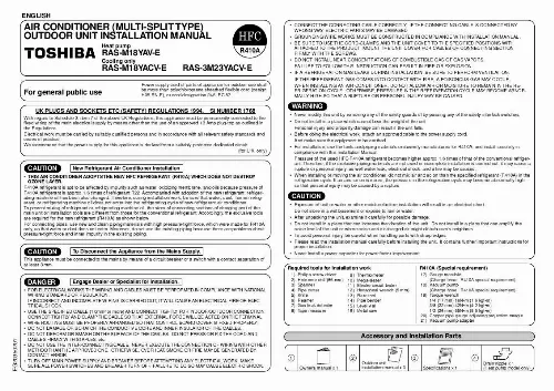
· There must be sufficient spaces for carrying the unit into and out of the site. · A place where the drain water does not raise any problem. In the case of flaring for R410A with the conventional flare tool, pull out it approx. 0,5 mm more than that for R22 to adjust to the specified flare size. The copper pipe gauge is useful for adjusting projection margin size. A · Install the provided drain nipple in the hole of the bottom plate. · Perform proper drainage processing using a drain hose sold separately or one on the market. (Inner diameter : 16 mm) · Do not use an ordinary hose on the market, because it tends to get flat and as a result, it prevents water from draining. Piping connections to the outdoor unit should be arranged in the sequence A, B, C, starting from the bottom. (For each piping connection, the gas pipe is on the bottom and the liquid pipe is on the top. When multiple indoor units are to be connected to the outdoor unit, make the ends of the pipes and wires from each indoor unit to ensure that they will be connected to the outdoor unit correctly. (Problems caused by indoor units being connected to the outdoor unit incorrectly are very common in multiple-unit installations. The length and height difference of the connecting pipes between the indoor and outdoor units must be within the ranges indicated below. · Total piping length : Two room (A + B) Multi, Non. Additional refrigerant 30 m Three room (A + B + C) Multi, Non. Additional refrigerant 40 m C A · Minimum piping length : A or B or C = 2 m or more A or B = 7 m or more Outdoor for one unit for heat pump unit · Maximum indoor piping length : A or B or C = 20 m or less B · Maximum piping height difference : A or B or C = 10 m or less · Maximum piping / height difference between two rooms = 10 m or less 4. If the outdoor unit is to be mounted on a wall, make sure that the platform supporting it is sufficiently strong. The platform should be designed and manufactured to maintain its strength over a long period of time, and sufficient consideration should be given to ensuring that the outdoor unit will not fall. When the outdoor unit is to be mounted high on a wall, take particular care to ensure that parts do not fall installer is protected. When doing installation work on level ground, it is usual to wiring and piping connections to the indoor units. And/then make to the outdoor unit. [...] IF INCORRECT AND INCOMPLETE WIRING IS CARRIED OUT, IT WILL CAUSE AN ELECTRICAL FIRE OR ELECTRICAL SHOCK. · USE THE SPECIFIED CABLE (1,0mm2 or more) AND CONNECT TIGHTLY FOR INDOOR/OUTDOOR CONNECTION. CONNECT TIGHTLY AND CLAMP THE CABLE SO THAT EXTERNAL FORCE WILL BE ACTED ON THE TERMINAL. · WIRE ROUTING MUST BE PROPERLY ARRANGED SO THAT CONTROL BOARD COVER IS FIXED PROPERLY. · DO NOT DAMAGE OR SCRATCH THE CONDUCTIVE CORE AND INNER INSULATOR OF THE CABLES. · DO NOT DEFORM OR SMASH ON THE SURFACE OF THE CABLES. DO NOT PRESS OR FIX THE CORD AND CABLES FIRMLY WITH STAPLES, etc. · DO NOT USE THE INTER-CONNECTING CABLE. NEVER EXECUTE THE CONNECTION OF WIRING WITH OTHER METHOD THAN THE APPROVED ONE. OTHERWISE, OVERHEAT, SMOKE OR FIRE MAY BE GENERATED BY CONTACT ERROR. · TURN OFF MAIN POWER SUPPLY AND BREAKER BEFORE ATTEMPTING ANY ELECTRICAL WORK. MAKE SURE ALL POWER SWITCHES AND BREAKER TURN OFF. FAILURE TO DO SO MAY CAUSE ELECTRIC SHOCK. Accessory and Installation Parts SPECIFICATIONS 1 Owner's manual x 1 2 Outdoor unit installation manual x 3 3 Specifications x 1 4 Drain nipple x 1 (Heat pump model only) Refrigerant Piping · Piping kit used for the conventional refrigerant cannot be used. · Use copper pipe with 0,8 mm or more thickness. · Flare nut and flare works · Flare nut and flare works are also different from those of the conventional refrigerant. Take out the flare nut attached to the main unit of the air conditioner, and use it. Optional Installation Parts (Separate Sold) Parts name RB-M43RE RB-M34EE Reducer (Ø12,7 Ø9,52) Expander (Ø9,52 Ø12,7) · Flaring size : A (Unit : mm) Outer dia. of copper pipe R410A 6,35 9,52 12,7 9,1 13,2 16,6 A +0 - 0,4 R22 9,0 13,0 16,2 Bottom plate Drain nipple Drainage Ø25 Drain hose sold separately or one on the market. Refrigerant Piping Connection CAUTION KEEP IMPORTANT 4 POINTS FOR PIPING WORK 1. Take away dust and moisture. (Inside of the connecting pipes) 2. Tight connection (between pipes and unit) 3. Evacuate the air in the connecting pipes using VACUUM PUMP. Check gas leak. (connected points) * Installation Place · A place which provides the spaces around the outdoor unit. · A place where the operation noise and discharged air do not disturb your neighbors. · A place which is not exposed to a strong wind. · A place which does not block a passage. [...]..
Téléchargez votre notice ! Téléchargement gratuit et sans inscription de tous types de documents pour mieux utiliser votre climatiseur TOSHIBA RAS-M18YA-CVE : mode d'emploi, notice d'utilisation, manuel d'instruction. Cette notice a été ajoutée le Vendredi 2 Février 2011.
