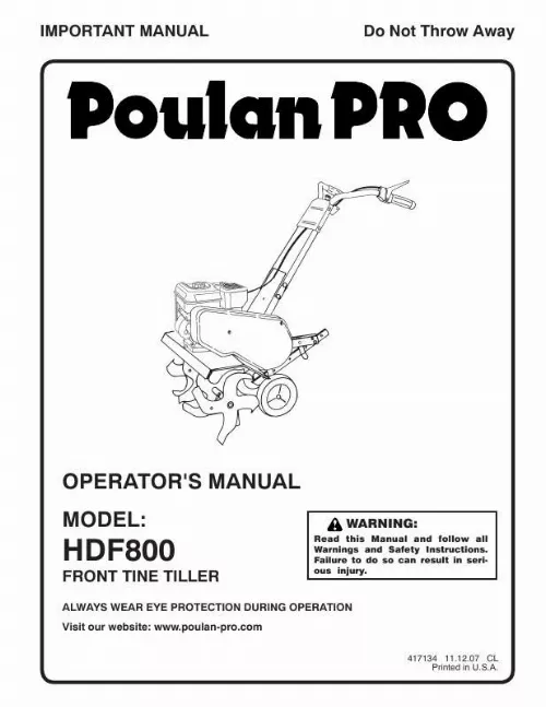
Notice POULAN HDF800
Liens commerciaux


Extrait du mode d'emploi POULAN HDF800
Les instructions détaillées pour l'utilisation figurent dans le Guide de l'utilisateur.
IMPORTANT: WHEN UNPACKING AND AS SEMBLING TILLER, BE CAREFUL NOT TO STRETCH OR KINK CABLE(S). INSTALL DEPTH STAKE ASSEMBLY (See Fig. 3) · · · · Loosen nut "A". Insert stake support between engine bracket halves with stake spring down. Bolt stake support to engine brackets with bolts, lock washers and nuts. Tighten securely. Tighten nut "A". Depth stake must move freely. If it does not, loosen support bolt. ENGINE BRACKET HALVES NUT "A" · · · · · Cut cable ties securing handles. Slowly lift handle assembly up, route cable(s) as shown and align handle holes with handle panel hole and slot. Loosely assemble hardware as shown. Be sure the shorter (1" long) hex bolt is assembled in lower hole of handle. Repeat for opposite side. Tighten all hardware securely. Cut cable ties securing tiller to skid and remove tiller from skid. Remove screws securing depth stake to skid and discard the screws. NUT LOCK WASHER TILLER HANDLE FLAT WASHER HEX BOLT 5/16-18X1-1/4" HEX BOLT 5/16-18X1" 0205 1 de pt h_ sta ke _ 4 DEPTH STAKE DEPTH STAKE SUPPORT SUPPORT BOLT HEX BOLTS, LOCK WASHERS, AND HEX NUTS STAKE SPRING HANDLE PANEL FIG. 3 HANDLE HEIGHT · Handle height may be adjusted to better suit operator. (See "HANDLE HEIGHT" in the Service and Adjustments section of this manual). Tilling width may be adjusted to better handle your tilling conditions (See "TINE ARRANGEMENT" in the Service and Adjustments section of this manual). Check tine operation before first use. (See "TINE OPERATION CHECK" in the Service and Adjustments section of this manual). CABLE(S) TILLER HANDLES HANDLE PANEL BOLTS TILLING WIDTH · TINE OPERATION · FIG. 2 5 OPERATION KNOW YOUR TILLER READ THIS MANUAL AND SAFETY RULES BEFORE OPERATING YOUR TILLER. Compare the illustrations with your tiller to familiarize yourself with the location of various controls and adjustments. Save this manual for future reference. These symbols may appear on your Tiller or in literature supplied with the product. Learn and understand their meaning. FORWARD TINE CONTROL REVERSE TINE CONTROL CHOKE CONTROL DEPTH STAKE THROTTLE CONTROL TINE SHIELD RECOIL STARTER HANDLE TINES FIG. 4 MEETS ANSI SAFETY REQUIREMENTS Our tillers conform to the safety standards of the American National Standards Institute. CHOKE CONTROL - Used when starting a cold engine. DEPTH STAKE - Controls forward speed and the depth at which the tiller will dig. [...] IMPORTANT: THIS UNIT IS EQUIPPED WITH AN INTERNAL COMBUSTION ENGINE AND SHOULD NOT BE USED ON OR NEAR ANY UNIMPROVED FOREST-COVERED, BRUSHCOVERED OR GRASS COVERED LAND UNLESS THE ENGINE'S EXHAUST SYSTEM IS EQUIPPED WITH A SPARK ARRESTER MEETING APPLICABLE LOCAL LAWS (IF ANY). IF A SPARK ARRESTER IS USED, IT SHOULD BE MAINTAINED IN EFFECTIVE WORKING ORDER BY THE OPERATOR. IN THE STATE OF CALIFORNIA, A SPARK ARRESTER IS REQUIRED BY LAW (SECTION 4442 OF THE CALIFORNIA PUBLIC RESOURCES CODE). OTHER STATES MAY HAVE SIMILAR LAWS. FEDERAL LAWS APPLY ON FEDERAL LANDS. SEE YOUR AUTHORIZED SERVICE CENTER/DEPARTMENT FOR SPARK ARRESTER. TABLE OF CONTENTS SAFETY RULES. 2 PRODUCT SPECIFICATIONS. 3 CUSTOMER RESPONSIBILITIES. 3 ASSEMBLY. 4-5 OPERATION. 6-9 MAINTENANCE SCHEDULE. 10 MAINTENANCE. 10-12 SERVICE & ADJUSTMENTS. 12-14 STORAGE. 15 TROUBLESHOOTING. 16 WARRANTY. 17 3 ASSEMBLY Your new tiller has been assembled at the factory with exception of those parts left unassembled for shipping purposes. To ensure safe and proper operation of your tiller all parts and hardware you assemble must be tightened securely. Use the correct tools as necessary to insure proper tightness. TOOLS REQUIRED FOR ASSEMBLY A socket wrench set will make assembly easier. Standard wrench sizes are listed. (1) Utility knife (1) Screwdriver (2) 1/2" wrenches FRONT overhead_views_8 LEFT RIGHT OPERATOR'S POSITION (See Fig. 1) When right or left hand is mentioned in this manual, it means when you are in the operating position (standing behind tiller handles). OPERATOR'S POSITION FIG. 1 CONTENTS OF HARDWARE PACK (2) Hex Bolts 5/16-18 x 1 (4) Washers 3/8 x 7/8 x 14 (4) Hex Bolts 5/16-18 x 1-1/4 (6) Lock Washers 5/16 (6) Hex Nuts 5/16-18 4 ASSEMBLY UNPACK CARTON & INSTALL HANDLE (See Fig. [...]..
Téléchargez votre notice ! Téléchargement gratuit et sans inscription de tous types de documents pour mieux utiliser votre POULAN HDF800 : mode d'emploi, notice d'utilisation, manuel d'instruction. Cette notice a été ajoutée le Lundi 1 Janvier 2011.
Vous pouvez télécharger les notices suivantes connexes à ce produit :


