Pièces détachées DE DIETRICH DHD506XU1
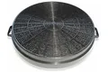
Filtre charbon pour hotte de cuisine DE DIETRICH DHD506XU17,55€ *
7,55€ *
★★★★★
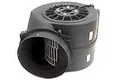
Moteur pour hotte de cuisine DE DIETRICH DHD506XU130,07€ *
30,07€ *
★★★★★
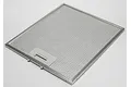
Filtre metallique pour hotte de cuisine DE DIETRICH DHD506XU18,52€ *
8,52€ *
★★★★★
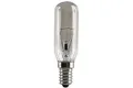
Ampoule pour hotte de cuisine DE DIETRICH DHD506XU13,91€ *
3,91€ *
★★★★★
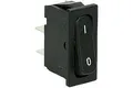
Interrupteur pour hotte de cuisine DE DIETRICH DHD506XU16,21€ *
6,21€ *
★★★★★
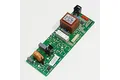
Carte pour hotte de cuisine DE DIETRICH DHD506XU127,50€ *
27,50€ *
★★★★★
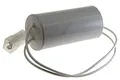
Condensateur pour hotte de cuisine DE DIETRICH DHD506XU16,58€ *
6,58€ *
★★★★★
Toutes les pièces détachées
* Prix indicatif de vente, le prix exact sera affiché après que vous ayez saisi la référence de votre appareil.


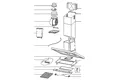
Extrait du mode d'emploi DE DIETRICH DHD506XU1
Téléchargez votre notice ! Téléchargement gratuit et sans inscription de tous types de documents pour mieux utiliser votre hotte DE DIETRICH DHD506XU1 : mode d'emploi, notice d'utilisation, manuel d'instruction. Cette notice a été ajoutée le Vendredi 10 Octobre 2010.
Vous pouvez télécharger les notices suivantes connexes à ce produit :


Envoyer vos modes d'emploi - Foire aux questions - Dernières recherches - Derniers ajouts - Sitemap - Contactez-nous - Conditions générales - Politique de cookies
Copyright - Tous droits réservés.
Les noms de marques cités appartiennent à leurs propriétaires respectifs.