Mes Notices

600 000 notices et 900 000 pièces détachées électroménager

Notice AKAI AT 901

Télécharger la notice

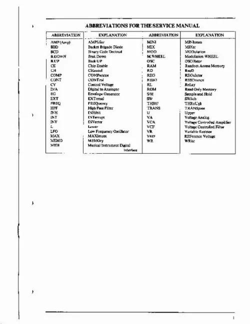
Extrait du mode d'emploi AKAI AT 901

Les instructions détaillées pour l'utilisation figurent dans le Guide de l'utilisateur.

•--* Co-Cs 8 4 Piano 2 C. -Ce C2-C7 Cj-Ca C4-C9 Fig. 4-1 V- PRINCIPAL PARTS LOCATION CHORUS PCB LIOI2B5O3O OPERATION (B) LIOI2A5O6O PCB LI0I2A5040 OPERATION(A) PCB POWER TRANSFORMER FILTER PCB L600I05080 POWER SUPPLY LI0I2BS050 PCB Fig. 5-1 -SERVICE MANUAL- VI. ADJUSTMENT 6-1. BALANCE OF ± 6V ON THE POWER SUPPLY PC BOARD Fig. 6-1 POWER SUPPLY PCB Adjustment Points 1) Connect a Digital DC Voltmeter between Pin [T] (+6V) and Pin 0 (GND) of connector P4 on the POWER SUPPLY PCB as shown Fig. Digital DC Voltmeter to Pin [4]. 3) Adjust VRI so that the Voltage Value at Pin | land 2) Read the + Voltage Value at the Pin [T|, and connect a Pin GQ are equal or within ± 0. OFF-SET OF FINAL VCA ON THE VOICE PC BOARD TP. O IC4l > IC5 ICI3 TPI > ice I IC10 I BALANCE > ic9 I CLIPPING LEVEL VR2 ■ I kHz AUDIO SIGNAL FROM OSC CLIPPING LEVEL Fig. 6-3 CHORUS PCB Adjustment Points and Instrument Connection 1) Set CHORUS switch to "2". 2) Connect an oscilloscope between TPI and GND on the CHORUS PC Board. 6-4 the oscilloscope is clipped a bit. 4) Adjust VR1 so that the Clipping level at upper side and lower side of the waveform are the same clipping level. 5) Connect an oscilloscope between TP2 and GND, and adjust VR2 as same manner as VR1. 3) Connect an Audio Signal Generator to Pin [I] and||] of connector PI on the CHORUS PC Board, and supply 1 kHz Audio Sine wave signal, and Adjust output level control of Audio Generator, so that the waveform on 6-4. OFF-SET OF IC6 (LF356) ON THE CPU PC BOARD \ VR I /off set □ Fig. 6-5 CPU PCB ADJUST POINT 1) Set to center position of VR1 on the CPU PC Board. SERVICE MANUAL- VII. [...] 4-2 and 6-0 split modes, arpeggia tion affects the lower split only. GTT OFF FREQ: To Set a cut off frequency oftheVCF(LPF). RESONANCE: To boosts the Amplitude of frequencies near the cut off frequency setting. ICY FOLLOW: To change the cut off fre quency according to the key played (higher or lower note) to maintain the same timbre. CO MOD: To produce musically useful timbre shifts. I-PF: To set a cut off frequency of the high pass filter. EG POLARITY SELECT BUTTON and IN DICATORS EG ASSIGNMENT/SELECTION BUTTONS and INDICATORS ARPEGGIO SPEED CONTROL KNOB EG PARAMETER SET-UP KNOBS MASTER LEVEL CONTROL SPUT BALANCE LEVEL CONTROL UNISON MODE SELECT BUTTON and INDICATORS AUTO TUNE BUTTONWHEEL UPPER/LOWER SELECT BUTTON and INDICATORS PINCH BEND DEPTH CONTROL KNOB Sets the amount of pitch change. ATTCK: DECAY: SUSTAIN: Sets the amount of time (T1). Sets the amount of time (T2). Sets the level. Sets the amount of time (T3) after a key is released. To change the pitch PITCH BEND WHEEL — RELEASE: CUT OFF FREQUENCY CONTROL KNOB — NOISE and SAMPLE! I INPUT CONTROL BUTTONS To select the Bank and Preset Number. DEPTH LEVEL: Sets the overall amplitude of the maximum deflection and also the sustain level. PROGRAM SELECT BUTTON when it rotated to "MAX" direction. MODULATION WHEEL The modulation wheel has no effect when it rotated to "MINI" direction, add modulation SPLIT MODE ON/OFF BUTTON NUMERIC DISPLAY To Select Tape Interface. To Sets MIDI channels. To Sets and Select Split preset CATORS SPUT MODE SELECT BUTTON and INDI VCO WAVEFORM SELECT BUTTON and INDICATORS - WRITE BUTTON COMPERE/EDIT SELECT BUTTONS and INDICATORS RECAUJKEY TRANS - CASSETTE INTERFACE SELECT BUTTON Fig. 3-1 -SERVICE MANUAL- IV. THE KEYBOARD REACTION-SHIP TO EQUALLY TEMPERED SCALE FREQUENCIES AND MUSICAL-NOTATION. - Piano keyboard - oeofE mil CoD<^oFoGoMoClD,ElF,61A)B1CAEaF262A2B2C303E3F3G3A3B3C,CU^F4MAC9D9E9F9G5As% PfffTtTT ii??° »e?1 I I I I I I I I I I I I I I I I I I I I I I I I I I I I I I I I I I I I I I I I I I I I I I I I I I I I I I I I I I I I I I I I I I I | I I I ! * 5 & S - 8 2 S 5 3 = » 5 15 ^ 5 £ ♦ S « IS * S * S 5 S S S 2 S g " " " " " " "-" -M-N -ro-w-l--w -* *?? "-"** ? fPr??? ? »S*SoS*«°**5o*°S--oo*wae»t5o5i*o*»«o«Hj,^ul|0^00,ow0ffl00_owo^«oo-tow. [...]..

Téléchargez votre notice ! Téléchargement gratuit et sans inscription de tous types de documents pour mieux utiliser votre lecteur dvd AKAI AT 901 : mode d'emploi, notice d'utilisation, manuel d'instruction. Cette notice a été ajoutée le Mercredi 10 Octobre 2017.

Le mode d'emploi AKAI AT 901 vous rend service

L'image diffusée par votre lecteur DVD est en noir et blanc, cela faisant suite à une non-utilisation prolongée de votre appareil. Votre lecteur DVD ne s'allume plus, bien que ce dernier soit correctement alimenté. Le voyant indiquant le démarrage de votre appareil ne s'enclenche plus quand vous mettez en marche votre lecteur DVD. Le mode d'emploi de votre AKAI AT 901 vous donnera les informations nécessaires pour remédier aux différentes pannes concernant le démarrage ou bien la diffusion d'image de votre appareil. Vous souhaitez en savoir plus sur les différents branchements à effectuer afin d'utiliser votre appareil dans de bonnes conditions. Vous souhaitez en savoir plus sur les différentes fonctionnalités proposées par votre lecteur DVD. Consultez la notice d'utilisation de votre AKAI AT 901 afin d'en savoir plus sur les différents paramétrages de votre lecteur DVD. Vous y trouverez également des informations concernant les différents branchements et les pièces détachées nécessaires au bon fonctionnement de votre appareil.

Liens commerciaux